
We're Different

History of CSS
Beginning with the patent granted in 1896 by American civil engineers James H. Watson and Stanley Simpson, CSS was primarily used for small drainage ditches in North America until the 1930s. By the late 1900s, the maximum span (width) had been expanded to 11 m, expanding its application to small bridges, passageways, and military facilities (ammunition depots). Beginning in the 2000s, the span was expanded to 23 m, broadening its application scope to include ecological tunnels, mine stockpiles, reclaim tunnels, and military facilities (hangars). Between 2014 and 2016, DAEDOTech® successfully researched, developed, and commercialized extra-wide corrugated steel plates (EXSCor), expanding the maximum span to 40 m. With the expansion of the span, it can now withstand the maximum loads of mining trucks such as the CAT 797F (approximately 620 tons) and EURO LM71, which were previously unsuitable, and is now competitive in terms of economy, stability, and constructability compared to multi-stage concrete structures. Furthermore, EXSCor®, an ultra-thin corrugated steel plate, is listed as a construction method and product according to design standards in Korea (KDS, KCS), as well as the U.S. AASHTO LRFD and ASTM A796M.
General Infomation
Corrugated steel plates are manufactured in a factory with consistent strength, significantly increasing their rigidity compared to raw steel. Standard steel (pitch: 150 mm, depth: 50 mm) exhibits a 92-fold increase in rigidity, large steel (pitch: 381 mm, depth: 140 mm) exhibits an 842-fold increase in rigidity, and extra-large steel (EXSCor) (pitch: 500 mm, depth: 237 mm) exhibits a 2,466-fold increase in rigidity. The manufacturing process is as follows:
-
By manufacturing corrugated steel plates with increased rigidity,
-
Process the curvature to meet the requirements of the drawing,
-
Create bolt holes to use during assembly.
-
To improve durability, it is galvanized before being brought to the site.
-
On-site assembly is completed by connecting with high-strength bolts.
-
After waterproofing the area around the bolt and the overlapping area of the corrugated steel plate (roof tile assembly area),
-
The structure is completed by filling and compacting backfill materials according to the requirements specified in the structural calculations and specifications.


Solution Improvement
We performed joint tests, bending tests, and box-shaped haunch tests, which are the most important factors for ensuring stability when designing corrugated steel plates, and applied verification values through tests on various materials (KS D 3503 fy: 275 MPa, fy: 315 MPa, fy: 450 MPa) and thicknesses (1.6 mm to 10 mm), satisfying the steel structure design standards (KDS 14 31 10: 2017: Ministry of Land, Infrastructure and Transport), road construction standard specifications (KCS 11 40 10: 2016: Ministry of Land, Infrastructure and Transport), and national defense and military facility standards (DMFC 4-10-70: 2009: Ministry of National Defense). In the case of overseas exports, we export in compliance with ASTM A796M, AASHTO M167, and AS/NZS 2041.1: 2011.


Bolt Seam Strength

Bending Moment

Hunch_Bending Moment

In addition, by producing and commercializing the ultra-thin type (EXSCor: Pitch: 500mm, Depth 237mm), which only four companies in the world produce, we have secured the production capacity and engineering capability of corrugated steel plates that are economical and more stable by increasing the steel consumption by only 8-9% compared to the existing large-thin type (Pitch: 381mm, Depth 140mm), and securing the rigidity of the cross-sectional second moment of inertia about three times.
Hunch_Bending Moment Lab. Motion Picture
3 Times Increased

Typical Section Library Service
We have optimized the rise ratio of the cross-section to the span (EXSCor®) along with the increased rigidity of the super-span type, allowing us to proactively provide our customers with the cross-sections they desire in response to the many changes in civil engineering conditions. Based on each span, from 2m to 40m, we have configured 8-9 optimal cross-section ratios (30% to 85% / Box shape: 20% to 65%), and we have approximately 440 typical cross-section drawings (Typical Section Library), enabling us to provide our customers with CAD files in a timely manner. Furthermore, we provide the quantity of corrugated steel plates and optimal soil cover for each cross-section, providing them with OCT results during the initial planning and design stages. *Please consult with a DAEDOTech® engineer regarding requests for the Typical Section Library when establishing cross-section plans.


Solution Engineering Service
We provide a one-stop service through the OCT Program (Optimization Comparison Table). The OCT Program is a smartphone (Android Version) and web-based program that allows all of our engineers to ① select the optimal cross-section in real time based on the on-site requirements through a library database of 395,872 items, ➞ ③ When selecting the optimal cross-section, we fully reflect the on-site conditions through the selection of steel type, backfill material, and backfill compaction degree (subbase material, subgrade soil, compaction rate 95%, 90%, 85%), ➞ ④ You can immediately receive information on the thickness of the corrugated steel plate (price comparison possible through weight calculation per meter) and the stability of the structure (safety factor notation according to the standards of each country). ➞ ⑤ In addition, by providing the stress value for the concrete foundation, we provide optimized engineering that secures the stability of the corrugated steel plate in relation to the overall construction cost, rather than simply comparing the construction costs of corrugated steel plates when establishing a structure plan. After planning the optimal structure using the OCT program, we provide all engineering services related to corrugated steel plates through an internal program that automatically generates structural calculations, design drawings, and quantity calculations.


Optimizing Comparison Report
*Section, Stability, Weight
Based on Web Version

FEA
① In cases of structures with partial earth pressure, excessively high soil cover, and special field conditions, ➞ ② We provide engineering services that predict the moment, axial force, and displacement of corrugated steel plate structures at each backfill stage through 3D, 2D Modeling computational analysis (FEA: Midas GTX, ABAQUS, Midas Civil, CANDE) and reflect them in structural calculations.


3D Scan Monitoring
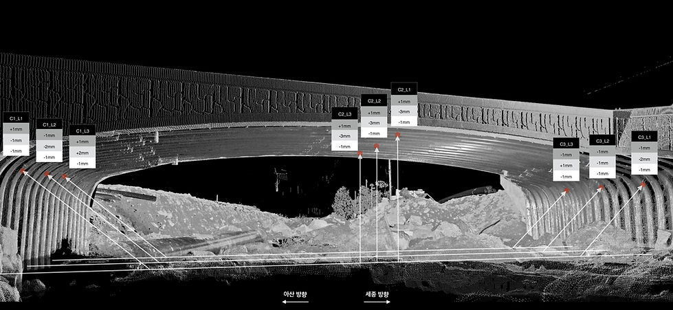
We are the first in the industry to introduce the latest 3D Scanning system (Leica® 3P, Cyclone®, TrueView®) technology to provide structural monitoring services. Through this, we provide 3D survey services for backfilling and post-completion displacements and final soil depths within ±3mm.


BIM (Building Information Method)
By being the first in the world to apply BIM from the corrugated steel plate planning stage, we aim to help clients fully understand the 3D on-site plan and every detail. We also minimize errors by accurately calculating the materials and costs involved during detailed design. Since the BIM detailed design stage is designed to LoD350*Level of Development or higher, object properties for all applied materials are provided. This allows us to design a system that even considers future maintenance. Furthermore, by providing detailed data for each construction stage, we eliminate errors on-site. We share this data with clients via an online viewer on their smartphones and PCs.


